Magnetic Bobbin Holder for Industrial Sewing Machine Parts: Install and Use
A magnetic bobbin holder is a small accessory with a measurable job: keep bobbins within reach, off the table, and free of lint. This reference covers holding-force figures, the exact installation sequence with gap tolerances, and the troubleshooting symptoms that tell you why a unit has shifted, tipped, or dropped a bobbin. It is written for line supervisors and technicians who need to specify and fit these industrial sewing machine parts without drilling into a machine casting.
Related guide: industrial sewing machine parts — types, fitting and machine compatibility.
Bobbin retrieval looks like a minor task until you count it. On a multi-color lockstitch station, an operator may change bobbins 40 to 80 times per shift. If each retrieval costs 20 to 30 seconds of searching, that is 15 to 40 minutes per machine per day. A magnetic holder does not change the sewing cycle, but it removes the search step, and on a full line that is the difference between a tidy station and a bottleneck.
The Real Cost of Bobbin Storage on a Production Floor
Bobbin storage fails for a physical reason: a bobbin is a small cylinder that rolls, and it sits on a machine that vibrates continuously. Any storage method that does not constrain the bobbin will eventually scatter it.
Each common method carries a specific, predictable cost:
- Loose in a drawer or bin. Colors mix and thread tails tangle. Retrieval time is variable, which is worse than slow, because it breaks the operator's rhythm.
- Stacked on the machine table. Bobbins roll into the fabric path, fall behind the machine, or pick up lint from the table surface.
- Shared central tray. Adds walking time and creates restocking disputes between shifts.
- Original bags or boxes. Retrieval is slow enough that operators stop using them and revert to the table.
A magnetic rack closes the gap by doing two things at once: it constrains each bobbin on a post so it cannot roll, and it mounts without fasteners so it can be repositioned when the line is rebalanced.
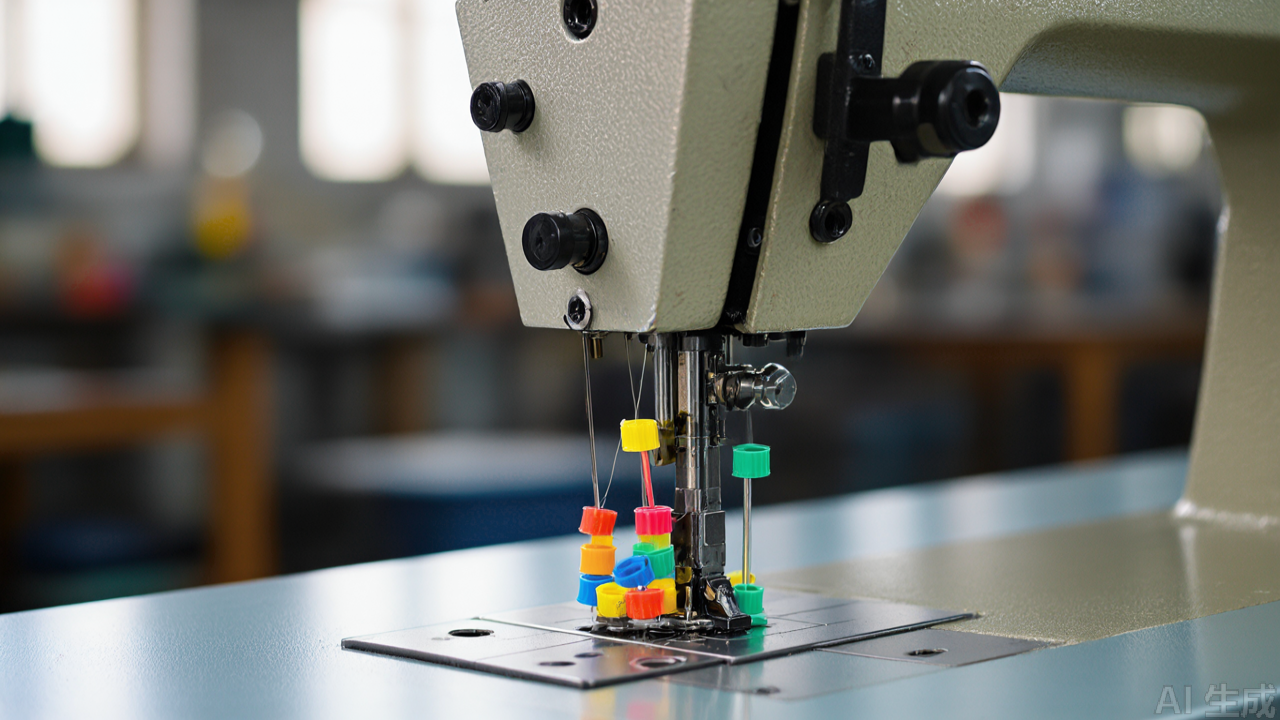
How a Magnetic Bobbin Holder Works
The mechanism has two independent parts. The magnet solves mounting. The posts or slots solve retention. Weak performance in the field is almost always a failure of one, not both, and identifying which one is failing is the first step in troubleshooting.
Magnetic circuit and holding force
The base contains one or more neodymium magnets, usually N35 to N42 grade in this product class, embedded in a plastic or metal housing. When the base contacts ferrous metal, the magnetic circuit closes through the workpiece and produces a normal (pull-off) force and a shear (slide) force. These are different numbers and both matter.
Typical figures for a compact holder with a base of roughly 40 to 60 mm diameter:
- Normal holding force (pull-off, perpendicular to surface): 15 to 30 kg (approximately 150 to 300 N) on clean, bare, low-carbon steel of 3 mm thickness or greater.
- Shear holding force (sliding, parallel to surface): typically 25 to 40 percent of the normal figure, so roughly 4 to 12 kg (40 to 120 N) for the same unit.
- Loaded weight of a full holder: a compact unit with 8 to 10 plastic bobbins weighs roughly 150 to 300 g. Metal bobbins add more; allow up to 500 g for a fully loaded metal-bobbin unit.
The margin between shear force and loaded weight looks generous on paper, and it usually is, provided the surface condition is right. The failure mode is not insufficient magnet strength. It is an air gap.
Why the air gap decides everything
Magnetic force falls off steeply with distance. For a typical neodymium assembly, holding force at a 0.5 mm gap is roughly 60 to 75 percent of the zero-gap value. At 1.0 mm it drops to roughly 40 to 55 percent. At 2.0 mm, most of the usable force is gone.
In a workshop, the gap is created by things you cannot see from arm's length:
- Paint and powder coat: commonly 0.05 to 0.15 mm per layer, more on heavily coated castings.
- Oil film: negligible in thickness but it allows the base to slide, which converts a static hold into a creeping one.
- Lint and fabric dust: accumulates under the base over a shift and can build to 0.3 to 0.8 mm within days if not cleaned.
- Surface curvature: a base that contacts a curved casting on only part of its area has an effective gap equal to the deepest point of the mismatch.
This is why a "strong magnet" claim is meaningless without a surface condition. A 25 kg magnet on a clean bare casting holds firmly. The same magnet on a powder-coated curved surface with a lint layer may hold less than 5 kg in shear, which is marginal for a loaded holder under machine vibration.
Bobbin retention
Above the base, posts or shaped slots locate each bobbin. Post diameter should match the bobbin bore with minimal clearance, generally within 0.3 to 0.5 mm. A post that is too thin lets the bobbin rock; a post that is too thick prevents full seating and leaves the bobbin sitting high, where it can be knocked off. Post height should be at least 60 percent of the bobbin height so the bobbin cannot tip off under lateral vibration.
Specifications and Materials
Figures vary between suppliers. The ranges below are typical for this class of accessory and should be verified against the actual unit before line-wide purchase.
- Mounting method: permanent magnet base, no fasteners, no adhesive.
- Magnet grade: N35 to N42 neodymium, single or multiple elements.
- Normal holding force: 15 to 30 kg on clean bare steel, 3 mm minimum thickness.
- Housing material: ABS or similar engineering plastic; some versions use a metal body with a plastic liner.
- Bobbin capacity: commonly 5 to 10 standard bobbins.
- Post diameter: sized for standard industrial bobbin bores; confirm against your actual bobbins.
- Compatible bobbins: standard plastic and metal bobbins for industrial lockstitch machines. Pre-wound and large-diameter types may not seat.
- Footprint: compact, typically small enough for a machine body side or top without blocking the needle sightline.
- Loaded weight: approximately 150 to 300 g with plastic bobbins, up to 500 g with metal bobbins.
Two specifications are worth requesting in writing from any supplier: normal holding force measured on a defined steel plate, and shear holding force for the same setup. If a supplier cannot provide both, treat the sample test on your own machine as the only valid data.
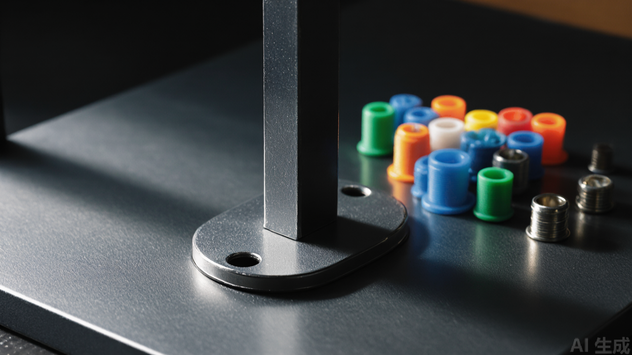
Installation: Step-by-Step with Tolerances
The sequence below assumes a compact magnetic holder in the 15 to 30 kg class. It takes about two minutes per machine once the surface is confirmed. Skipping steps is the main reason units drift or fall in service.
Step 1: Confirm the mounting surface
Test with a small reference magnet before anything else. The surface must be ferrous and at least 3 mm thick for full holding force. Below 2 mm, expect a significant reduction because the magnetic circuit saturates the thin material.
- Suitable: cast iron machine bodies, carbon steel table frames, iron brackets, mild steel plate.
- Not suitable: aluminum alloy castings, stainless steel (300 series), plastic housings, zinc die-cast covers.
If your machine body is aluminum, mount on a steel table edge or add a steel plate. Do not attempt to compensate with a stronger magnet; the surface is the limiting factor.
Step 2: Clean and measure the gap
Wipe the mounting area with a lint-free cloth. Remove oil film, lint, and fabric dust. If the surface is painted or powder coated, measure the coating thickness if you have a gauge, or test with a reference magnet against a bare metal area of the same machine for comparison.
- Target air gap: 0 to 0.2 mm for full rated force.
- Acceptable: up to 0.5 mm, with roughly 60 to 75 percent of rated force.
- Marginal: 0.5 to 1.0 mm, roughly 40 to 55 percent of rated force. Acceptable only for light loads or low-vibration positions.
- Reject: above 1.0 mm. Relocate to a bare metal area.
Step 3: Select the position
Position determines whether the holder survives a shift. The unit should be:
- Within reach of the operator's dominant hand without crossing the needle area.
- Outside the direct sightline to the needle and presser foot.
- Clear of the hand path during fabric handling, with at least 50 mm of clearance from the normal fabric feed zone.
- Away from the motor housing and any surface that exceeds roughly 60 degrees C in continuous operation. Sustained heat degrades neodymium magnets and reduces holding force permanently.
On a lockstitch machine, the side of the machine arm or the upper body usually works. On an overlock or coverstitch machine, the casting is more crowded; the front-left or rear side of the body is common, or the steel table edge if the machine body is aluminum.
Step 4: Attach and verify holding force
Place the holder on the cleaned surface and press down firmly. Then test before loading:
- Pull-off test: pull perpendicular to the surface with moderate force. The unit should not release.
- Shear test: push sideways with roughly 3 to 5 kg of force, which approximates a loaded holder under machine vibration. The unit should not slide.
- Rock test: press one edge down and the opposite edge up. Any rocking indicates a curved surface or a base that is not flat. Reject the position.
If the unit slides or rocks, do not proceed. Clean again, check for curvature, or relocate.
Step 5: Load and run-in
Insert bobbins and confirm each seats fully with no wobble. Then run the machine at normal production speed for at least 10 minutes and re-check the hold. Vibration reveals weak mounting faster than any static test. Re-check after the first full shift; a unit that has drifted by more than 1 mm in a shift will continue to drift.
Step 6: Set a loading convention
This is a management step, not a technical one, but it decides whether the accessory saves time. Agree on a rule for the line:
- Positions 1 to 3 for the colors currently running on that machine.
- Remaining positions for the next colors in the production sequence.
- Full bobbins only; empties go to a separate collection point.
Without a convention, the holder becomes a tidier version of the same mixed pile.
Suitable Machines and Fabrics
The holder does not interact with the sewing mechanism, so compatibility depends on two things: a ferrous mounting surface and bobbins that fit the posts.
Machines
- Lockstitch machines. The most common application. Large flat ferrous body area, frequent bobbin changes.
- Overlock machines (sergers). Multiple threads; a holder separates small bobbin threads from cone threads.
- Coverstitch machines. Similar to overlock, useful where several thread colors run at once.
- Other industrial machines with ferrous castings. Generally suitable if the mounting area is clear.
Fabrics and production types
- Multi-color work. Contrasting topstitching, binding, and decorative seams drive frequent bobbin changes. Largest time saving.
- Knits and stretch fabrics. Usually run on overlock and coverstitch machines with several threads, so thread organization matters more than raw change speed.
- Woven bulk production. Fewer changes, but the holder still prevents loss and lint contamination.
- Sampling and small-batch rooms. High change frequency and many colors; keeps the sample table workable.
Troubleshooting: Symptoms and Causes
Field problems with magnetic bobbin holders fall into a small number of patterns. Match the symptom to the cause before replacing the unit.
Symptom: holder slides slowly across the machine body over a shift
- Cause: oil film or lint under the base reducing friction, combined with machine vibration.
- Fix: lift the holder, degrease the base and the mounting surface, dry both, and re-seat. If sliding recurs within a shift, the surface is curved or the gap is too large.
Symptom: holder falls off during operation
- Cause: non-ferrous or thin mounting surface, or an air gap above 1.0 mm from paint or coating.
- Fix: relocate to a bare metal area at least 3 mm thick. Do not add adhesive; it increases the gap and reduces force further.
Symptom: holder tips forward when bobbins are removed
- Cause: overloaded unit or a base that contacts the surface on only part of its area.
- Fix: reduce the bobbin count to the rated capacity and check for surface curvature with the rock test.
Symptom: bobbins fall out during high-speed runs
- Cause: post diameter too small for the bobbin bore, post height below 60 percent of bobbin height, or oversized bobbins that do not seat fully.
- Fix: check post-to-bore clearance. If it exceeds 0.5 mm, the holder is not matched to your bobbins. Confirm the correct bobbin type with the supplier.
Symptom: bobbins wobble but stay seated
- Cause: post diameter slightly under bobbin bore, or a plastic housing that flexes under load.
- Fix: measure the bore and the post. If the housing flexes visibly when loaded, the unit will eventually crack at the post base; replace with a rigid-bodied version.
Symptom: holding force drops over weeks of service
- Cause: accumulated lint under the base, or heat exposure above roughly 60 degrees C from the motor housing or a nearby heat source.
- Fix: clean the base weekly. If the unit was mounted near the motor, relocate it. Neodymium magnets lose strength permanently above their maximum operating temperature, and this is not recoverable.
Symptom: thread tails catch on passing fabric
- Cause: holder mounted too close to the sewing area, with loose thread ends exposed.
- Fix: relocate at least 50 mm clear of the fabric feed zone and trim thread tails from stored bobbins.
Maintenance Schedule
Maintenance is minimal but should be scheduled rather than left to chance.
- Daily: remove loose thread tails and lint from the holder and the mounting surface.
- Weekly: lift the holder, wipe the magnetic base and the machine surface, re-seat, and re-check holding force by hand.
- Monthly: inspect posts and slots for wear or cracking, particularly on plastic-bodied units. Re-check post-to-bore clearance.
- As needed: when a line is rebalanced or a machine moves, lift the holder and reattach at the new position. No tools, no patching of screw holes.
One caution on cleaning: do not soak the magnetic base in solvent. Some magnet assemblies are not sealed against liquid ingress, and damage to the coating or adhesive reduces holding force permanently.
Selection Tips for Buyers
When comparing units from different suppliers, including a China sewing parts supplier, the differences are in the details rather than the concept. Use this checklist on a sample before committing to a line-wide order.
- Request both holding-force figures. Normal and shear, measured on a defined steel plate. A single "strong magnet" claim is not a specification.
- Test on your actual machine. Fit the sample to the exact machine model and surface you will use. Catalog figures assume ideal conditions.
- Send your bobbins to the supplier. Both plastic and metal, so post diameter and height can be confirmed against your actual stock.
- Inspect the magnet housing. Flat, fully covered base with no exposed magnet edges that could chip or corrode.
- Check post height and diameter. Target clearance within 0.3 to 0.5 mm of the bobbin bore, and post height at least 60 percent of bobbin height.
- Assess housing rigidity. A housing that flexes under load will crack at the post base. Rigid plastic or metal-bodied units last longer.
- Confirm batch consistency. For line-wide deployment, holding force and dimensions should be uniform across the batch. Ask about batch inspection.
- Evaluate as part of a broader parts strategy. A magnetic holder is a low-cost accessory compared with presser feet, feed dogs, or needle plates, but it should come from a supplier whose tolerances you trust for other industrial sewing machine spare parts.
Be realistic about the limits. This accessory will not improve stitch quality, reduce needle breakage, or substitute for correct tension settings. It solves one problem, bobbin accessibility and organization, and it solves it well. Factories already running a disciplined 5S program will see modest gains. Factories where bobbins currently live in a communal drawer will see the difference on the first shift.
For reference, a holder of this type is available under the PL strong-magnet bobbin rack line, item code 1688-0825, which follows the standard configuration described above.
Summary
A magnetic bobbin holder is a low-cost, low-risk addition to a sewing station. It requires no drilling, no screws, and no modification to the machine, and it can be relocated in seconds when a line is rebalanced. The installation rules are specific: confirm the surface is ferrous and at least 3 mm thick, keep the air gap at or below 0.2 mm for full rated force, position the unit at least 50 mm clear of the fabric feed zone, and verify both pull-off and shear hold under production vibration before trusting it with a full load.
For garment factory managers and technicians evaluating industrial sewing machine parts, the practical test is straightforward. Fit one holder to a machine running multi-color work, brief the operator on a loading convention, and measure the change in bobbin retrieval time over a week. If the holder stays in place and the operator stops searching through a drawer, it has done its job. If it slides or tips, the air gap or the mounting surface is the cause, and the troubleshooting sequence above will identify which.
Need this part for your workshop?
Get a Free Quote on WhatsApp: +86 137 3825 6697Browse the full catalog at pinseam.com · Free 2026 full catalog (PDF) · Related guide: industrial sewing machine parts
📢 New arrivals & factory updates on Telegram — join our channel
Edited by the technical team at PL (Professional Leader) — high-quality sewing machine accessories from China. About our factory | Catalog: pinseam.com | WhatsApp: +86 137 3825 6697 | Telegram: @plsewingparts
Explore Our Parts Guides
- multifunctional needle threader guide — how to use & choose
- jack multifunctional needle threader — one-second threading
- sewing machine accessories, needle threaders & thread guides
- industrial & magnetic seam guides
- presser foot guide: types & compatibility
- industrial presser feet for factory lines
- roller & rolled hemmer presser feet
- industrial sewing machine parts & spare parts
- wholesale sewing machine parts — PL (Professional Leader) factory direct
- about PL (Professional Leader) — Hangzhou Fubang, sewing parts brand since 2018
Questions about a specific part? Chat with us on WhatsApp +86 137 3825 6697 — factory direct, reply within hours.


Comments
Post a Comment