Industrial Sewing Machine Parts: Tolerances, Failure Modes, and Setup for Smart Manufacturing
Most stitch defects on a modern lockstitch, overlock, or coverstitch machine trace back to four consumable components: the presser foot, feed dog, needle plate, and bobbin case. This article gives technicians and buyers the specific tolerances, part-number conventions, installation steps, and named failure modes needed to select, fit, and diagnose these industrial sewing machine parts — rather than general commentary on industry direction.
Related guide: presser foot — types, fitting and machine compatibility.
Presser Foot: Selection by Shank, Not by Machine Brand
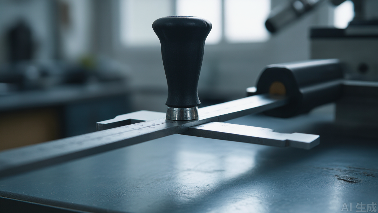
Presser foot fitment is determined by shank dimensions, not by machine brand name. Before ordering, measure the existing foot with a caliper.
- Low shank: shank height approx. 12.7 mm (1/2 in) from the bottom of the foot to the center of the screw hole. Common on domestic and light industrial machines.
- High shank: approx. 25.4 mm (1 in). Common on many industrial lockstitch platforms.
- Slant shank: shank angled approx. 45 degrees. Found on certain older industrial models.
- Shank slot width: typically 5.0 mm or 6.0 mm. A 0.2 mm oversize slot causes the foot to rock under load; an undersize slot will not seat.
For presser foot types, match the foot to the material and seam, not to convenience:
- Standard flat foot (e.g., P351, P351L): general woven fabrics, medium weight.
- Compensating foot (left/right, e.g., P360, P361): topstitching, edge joining, zipper insertion. The single-toe design keeps the seam line visible.
- Teflon-coated foot (e.g., P351T): PU, coated fabrics, vinyl, and any material that drags or sticks under a bare metal foot.
- Roller foot (e.g., P363): leather, vinyl, and heavy coated materials where friction causes the top ply to shift.
- Narrow hemming foot (e.g., P366, sizes 2 mm–10 mm): fine hems on lightweight fabric; the scroll fold determines the finished hem width.
Common presser foot failure modes
- Shank slot wear: the slot elongates after extended use, allowing the foot to tilt. Symptom: inconsistent stitch length and skipped stitches on one side of the seam. Replace when slot clearance exceeds 0.3 mm.
- Sole grooving: a groove wears into the underside where the feed dog contacts. Symptom: fabric snagging or a visible track on delicate material. Inspect with a straightedge; replace if the groove depth exceeds 0.1 mm.
- Coating flaking (Teflon feet): coating wears through at the toe. Symptom: intermittent drag on coated fabric. Replace at first sign of exposed base metal.
- Bent toe: caused by needle strikes or forced fabric. Symptom: the foot contacts the needle plate on one side. Check flatness on a surface plate.
Feed Dog: Tooth Geometry and Height Setting
Feed dog selection is defined by three parameters: tooth pitch, tooth height, and slot configuration. Using the wrong geometry is a common cause of puckering or material damage that technicians misdiagnose as tension problems.
- Fine-tooth (e.g., 14–20 teeth per inch): lightweight and medium woven fabrics. Reduces marking and puckering.
- Coarse-tooth (e.g., 8–12 teeth per inch): heavy woven, denim, canvas. Provides grip without slipping.
- Rubber or coated feed dogs: leather, vinyl, and coated materials where metal teeth would mark the surface.
- Differential feed dogs (overlock): matched to the machine's differential ratio range; check the part number against the machine's feed dog chart before ordering.
Feed dog height setting
Feed dog height is measured from the top of the tooth to the top surface of the needle plate, with the feed dog at its highest point in the cycle.
- Light fabric: 0.8–1.0 mm above the needle plate.
- Medium fabric: 1.0–1.2 mm.
- Heavy fabric: 1.2–1.5 mm.
To set: loosen the feed dog screws, rotate the handwheel to bring the feed dog to its highest point, place a straightedge across the needle plate, and measure with a feeler gauge. Tighten screws and re-check — the feed dog can shift during tightening.
Common feed dog failure modes
- Worn teeth: tooth tips round off, reducing grip. Symptom: stitch length shortens under load, especially on heavy material. Replace when tooth height drops below 0.6 mm.
- Bent feed dog: caused by needle strikes or jammed material. Symptom: fabric feeds at an angle. Check alignment against the needle plate slot.
- Slot interference: feed dog contacts the needle plate slot edges. Symptom: audible scraping and erratic feed. Verify slot clearance is 0.3–0.5 mm on all sides.
Needle Plate: Slot Condition and Hole Size
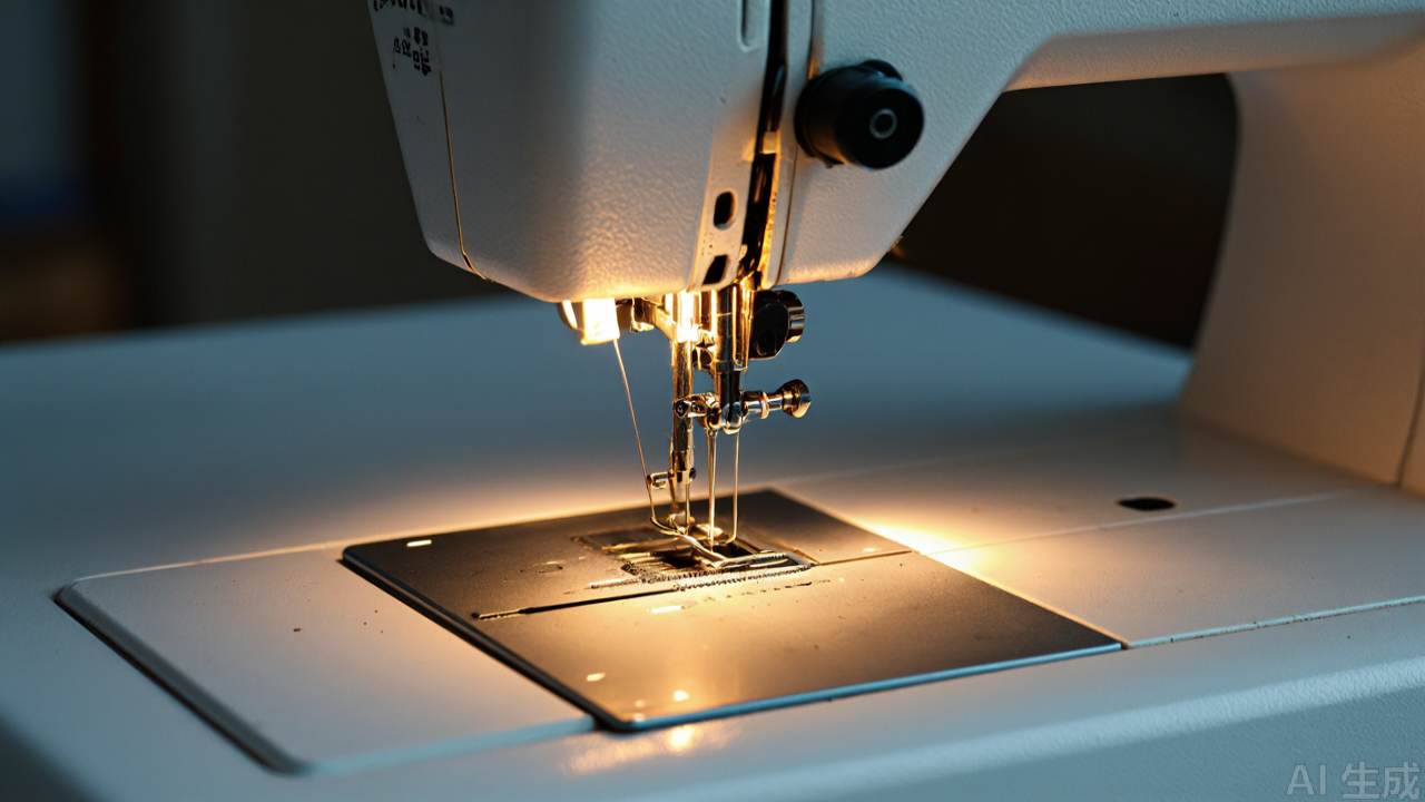
The needle plate controls fabric support and stitch formation. Two dimensions matter most: the needle hole diameter and the slot edge condition.
- Needle hole diameter: match to needle size. For a size 90/14 needle, the hole should be approximately 1.6–1.8 mm. An oversized hole allows the fabric to be pushed down, causing skipped stitches and flagging.
- Slot width: must match the feed dog width. A mismatch of more than 0.2 mm causes fabric to catch on the slot edge.
- Edge finish: the slot edge should be polished with no burrs. A burr will cut thread and fray fabric edges.
Common needle plate failure modes
- Needle strikes: the most common failure. The needle hits the plate edge, creating a burr or a dent. Symptom: thread breakage at the needle, frayed fabric. Inspect with a magnifier after any needle break.
- Slot wear: the feed dog wears the slot edges over time, widening the slot. Symptom: fabric snagging and inconsistent feed. Replace when slot width exceeds the feed dog width by more than 0.5 mm.
- Warping: caused by over-tightening or heat. Symptom: plate does not sit flat, causing fabric to lift. Check flatness on a surface plate.
Bobbin and Bobbin Case: Clearance and Tension
Bobbin-related defects — uneven stitches, thread nesting, and bobbin thread breaks — usually come down to two settings: bobbin case clearance and bobbin tension.
- Bobbin case clearance: the gap between the bobbin case and the hook race should be 0.05–0.10 mm. Check with a feeler gauge. Excessive clearance causes thread to slip under the case, producing loose stitches.
- Bobbin tension: with the bobbin case suspended by the thread, it should drop slowly under its own weight or require a slight tug. Adjust the tension screw in 1/8-turn increments.
- Bobbin winding: the bobbin should be wound evenly and not overfilled. An overfilled bobbin will not seat properly and causes tension fluctuation.
Common bobbin failure modes
- Bobbin case wear: the tension spring loses tension or the case develops a groove. Symptom: inconsistent bobbin tension that cannot be adjusted. Replace the case.
- Bobbin distortion: plastic bobbins warp under heat or pressure. Symptom: bobbin binds in the case. Check by inserting the bobbin into the case and spinning it — it should rotate freely with no wobble.
- Hook race wear: the hook race develops a groove from thread abrasion. Symptom: thread frays or breaks near the hook. Inspect the race under magnification; replace the hook assembly if grooved.
Installation Sequence and Verification
When replacing any of these components, follow a consistent sequence to avoid introducing new faults:
- Disconnect power and remove the needle. This prevents accidental needle strikes during adjustment.
- Remove the old component and inspect the mounting surface. Clean any lint, thread, or metal debris. A burr on the mounting surface will prevent the new part from seating correctly.
- Install the new component and tighten to specification. Presser foot screw: snug plus 1/4 turn. Feed dog screws: snug, then verify height before final tightening. Needle plate screws: snug in a cross pattern to avoid warping.
- Verify clearances with a feeler gauge. Feed dog to needle plate slot: 0.3–0.5 mm. Presser foot to needle plate: foot should rest flat with no rocking.
- Run a test seam on the actual production material. Check stitch length consistency, seam puckering, and thread tension. Adjust as needed before releasing to production.
Building a Spare Parts Standard
For factories standardizing their industrial sewing machine parts inventory, the practical approach is to document the following for each machine class:
- Presser foot shank type and slot width
- Feed dog tooth pitch, height, and slot configuration
- Needle plate hole diameter and slot width
- Bobbin size and bobbin case part number
- Replacement intervals based on stitch count or operating hours
PL manufactures presser feet, feed dogs, needle plates, bobbins, and hooks to these dimensional specifications; its full parts catalog is documented at pinseam.com. For any supplier, request dimensional drawings and sample measurements before committing to a batch, and verify the first delivery against those drawings.
The difference between a machine that runs reliably and one that generates constant quality issues is often measured in tenths of a millimeter at these four components. Documenting tolerances, inspecting on a schedule, and replacing on condition rather than on failure is the practical version of the smart manufacturing upgrade.
Need this part for your workshop?
Get a Free Quote on WhatsApp: +86 137 3825 6697Browse the full catalog at pinseam.com · Free 2026 full catalog (PDF) · Related guide: presser foot
📢 New arrivals & factory updates on Telegram — join our channel
PL (Professional Leader) supplies sewing machine parts for industrial lockstitch, overlock and interlock machines, including the industrial presser foot range, needle plates, feed dogs and related presser foot accessories.
Edited by the technical team at PL (Professional Leader) — high-quality sewing machine accessories from China. About our factory | Catalog: pinseam.com | WhatsApp: +86 137 3825 6697 | Telegram: @plsewingparts
Explore Our Parts Guides
- sewing machine accessories, needle threaders & thread guides
- industrial & magnetic seam guides
- presser foot guide: types & compatibility
- industrial presser feet for factory lines
- roller & rolled hemmer presser feet
- industrial sewing machine parts & spare parts
- wholesale sewing machine parts, factory direct
- about PL (Professional Leader)
Questions about a specific part? Chat with us on WhatsApp +86 137 3825 6697 — factory direct, reply within hours.


Comments
Post a Comment