Magnetic Seam Guide for Overlock and Lockstitch Machines: Installation and Setup
A magnetic seam guide for overlock and lockstitch machines is a small accessory that solves a persistent production problem: the fabric edge drifting into the cutter or away from the needle line. This article covers how the device works, its materials and adjustment range, and a complete step-by-step installation and tuning procedure. It also covers suitable machine types, fabric behaviour, common setup errors, and practical selection criteria for factory buyers.
Related guide: magnetic seam guide — types, fitting and machine compatibility.
The part discussed here is the PL second-generation edge guard and positioning gauge (item code 1688-0553), a metal bracket that mounts near the cutter or presser foot and physically limits how far the fabric edge can travel. It is not a motorised feeder and it does not replace operator skill, but on long production runs it removes one of the most common sources of rework in edge-finishing operations.
Why Fabric Edges Drift, and What a Magnetic Seam Guide Changes
On an overlock machine, the cutter trims the fabric edge immediately before the needle and looper form the stitch. The trimmed width is set by the distance between the fabric edge and the fixed cutter. If the operator feeds the fabric slightly off-line, the cutter takes more or less material than intended. The result is a wavy, over-trimmed edge, a seam that loses its allowance, or in the worst case a cut into the garment body.
Several factors make this drift worse:
- Knits and stretch fabrics that curl or relax as they pass the differential feed.
- Lightweight and slippery materials such as chiffon, silk, mesh, and lining fabrics.
- High sewing speeds on long runs, where small corrections come too late.
- Operator fatigue on repetitive edge-finishing tasks.
A magnetic seam guide addresses the problem mechanically rather than by eye. A metal plate sits just outside the cutter or alongside the presser foot and forms a hard stop. The fabric edge runs against this stop, so the amount entering the cutter stays constant regardless of small hand movements. The operator steers the fabric along a physical reference instead of judging the cut line visually.
It is worth being clear about the limits. A guide cannot correct a badly adjusted differential feed, a blunt cutter, or fabric that is being pulled sideways by incorrect tension. It reduces variation; it does not eliminate the need for correct machine settings.
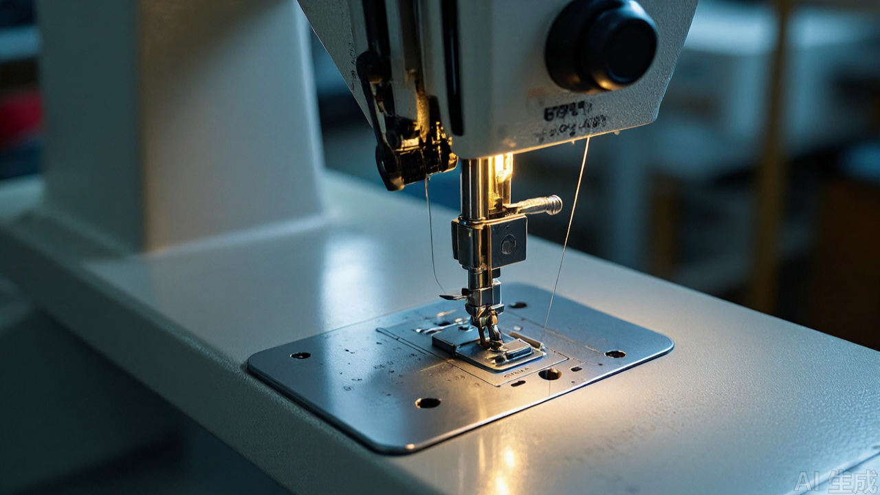
How the Second-Generation Edge Guard Works
The device is essentially a two-part assembly: a mounting body that fixes to the machine, and a thin guard plate that projects toward the cutter or needle line. The plate is the working surface. Its position relative to the cutter determines the trimmed width.
The guard plate as a physical limit
The plate sits on the outer side of the cutter path. When the fabric edge contacts it, the edge cannot move further inward. This fixes the trim width for the whole run. Because the plate is thin and sits close to the cutter, it does not interfere with the stitch formation or the looper threads.
Preset edge position instead of visual judgement
The second-generation design allows the plate to be set front-to-back and left-to-right before production starts. Once locked, that position defines the seam allowance. On a lockstitch machine used without a cutter, the same plate acts as an edge guide for consistent seam width, which is useful when sewing parallel rows or attaching trims.
What changed from the first generation
The first-generation part worked, but the plate was thicker and the adjustment range was narrower. The second generation reduces plate thickness and optimises the angle of the guard, so the fabric slides along it with less drag. The locking arrangement is also firmer, which matters because a guard that shifts mid-run is worse than no guard at all — it changes the trim width without warning.
Materials, Dimensions, and Adjustment Range
The body is metal, typically stainless steel or carbon steel with a plated finish. The guard plate is the wear part, since fabric runs against it continuously. Both surfaces are chosen for abrasion and corrosion resistance rather than appearance.
- Body: stainless steel or plated carbon steel, rigid enough to hold position under side load.
- Guard plate: thin metal sheet, ground and finished so the fabric edge does not snag or fray against it.
- Fasteners: machine screws matched to the mounting body; a spare set is worth keeping in the parts crib.
- Adjustment: front-to-back and left-to-right micro-adjustment to suit different seam allowances and fabric thicknesses.
Because mounting positions differ between machine models, buyers should confirm the screw hole layout near the presser foot and cutter before ordering. The manufacturer's fitment notes list common overlock and lockstitch configurations, but the physical check is what matters. A guide that cannot be mounted rigidly will not hold a setting.
For readers comparing this against other industrial sewing machine parts, the relevant comparison is not price per piece but stability of the setting over a shift. A guard that needs re-adjusting every hour costs more in downtime than it saves.
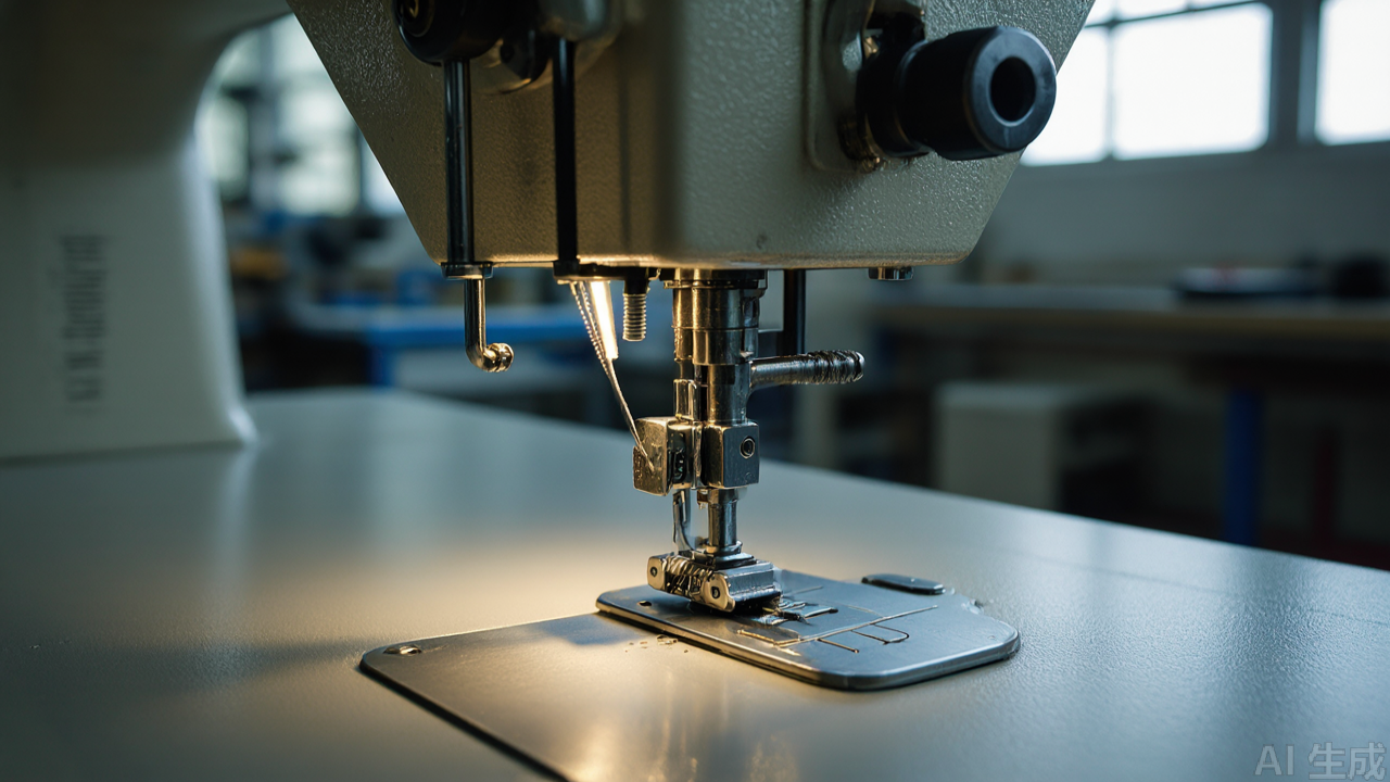
Step-by-Step Installation
The procedure below applies to overlock machines with a cutter and to lockstitch machines used for edge guidance. Work with the machine switched off and the needle removed if you are adjusting near the needle line.
Step 1: Identify the mounting point
Look for an existing screw hole on the machine body near the cutter or on the presser foot shank. Most industrial overlock machines have at least one tapped hole in this area, often used for optional attachments. If no hole exists, do not drill into the machine casting. Use a clamp-type adapter or a bracket that shares an existing fastener instead.
Step 2: Fit the body loosely
Attach the mounting body with the supplied screws, but leave them finger-tight. The body needs to move during adjustment, and tightening early makes the next steps harder.
Step 3: Set the guard plate position
Slide the guard plate so its working face sits just outside the cutter path, at the trimmed width you want. For a standard overlock seam allowance, start with the plate set so roughly the intended trim width of fabric passes the cutter. Move the plate in small increments; a 0.5 mm change is visible in the finished edge.
Step 4: Check clearance by hand
Turn the handwheel slowly through a full cycle. Watch the gap between the guard plate, the cutter, and the needle plate. There must be no contact at any point in the cycle. On overlock machines, also check that the plate does not obstruct the upper or lower looper path. If anything touches, back the plate off and reset.
Step 5: Test on scrap fabric
Run a strip of the actual production fabric through at normal speed. Measure the trimmed width at three points along the strip. If the width varies, the plate is either not parallel to the feed direction or not rigidly mounted. Adjust and repeat until the width is consistent.
Step 6: Lock and verify
Tighten all fasteners firmly. Run a second test strip and re-measure. Then run a short length at production speed, since vibration at speed can reveal a loose setting that a slow test does not.
Step 7: Record the setting
Note the plate position and the resulting trim width in the machine's setup log. When the guide is removed for a different operation, the setting can be restored quickly. This is a small habit that saves real time on machines running multiple styles.
Using the Guide in Production
Once installed, the guide changes how the operator handles the fabric. The edge is pressed lightly against the plate and the machine does the rest. A few practical points:
- Feed the fabric so the edge contacts the plate continuously, not intermittently.
- Do not push the fabric hard against the plate; excessive side pressure distorts knits and can cause the edge to ride up.
- On slippery fabrics, reduce speed slightly at the start of a run until the edge is seated against the plate.
- For curved seams, the guide is less useful — it works best on straight or gently curved edges.
In a batch production setting, the main gain is consistency between operators. Two operators using the same machine with the same guide setting produce the same trim width, which simplifies downstream assembly.
Suitable Machines and Fabrics
The guide is designed for the general mounting area near the presser foot and cutter, so it fits a broad range of machines. The list below covers typical applications.
- Overlock machines (sergers): the primary application. The guide controls trim width on knit and woven edge finishing.
- Lockstitch machines: used as an edge guide for consistent seam allowance, particularly on straight runs and topstitching.
- Coverstitch machines: fitment depends on the machine head; check clearance around the presser foot before ordering.
On the fabric side, the guide is most valuable on materials that misbehave at the cutter:
- Knits and jersey, which curl at the edge.
- Chiffon, silk, mesh, and other lightweight or slippery fabrics.
- Pile and plush fabrics used in home textiles and toys, where a miscut is expensive.
- Coated or laminated fabrics where the edge tends to stick or drag.
On heavy canvas or thick denim, the guide still works, but the plate must be set with more clearance and the operator should expect more drag. On very thick seams, the guard can interfere with the presser foot lift, so check the maximum fabric stack height before committing to a setting.
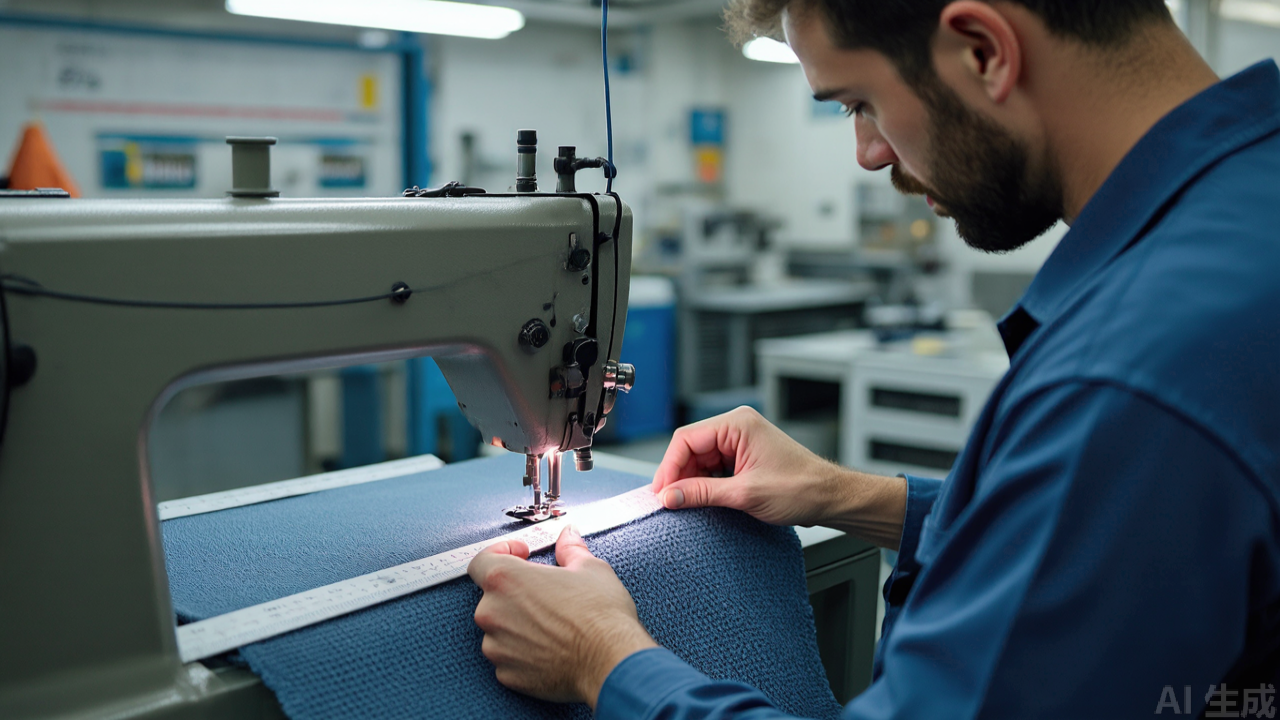
Common Installation Mistakes
Most problems with edge guides come from installation rather than the part itself. The recurring errors are:
- Mounting without checking clearance. A plate that touches the cutter or needle plate will damage both the part and the machine.
- Over-tightening before adjustment. This strips threads and makes fine positioning impossible.
- Setting the plate by eye only. Always verify with a measured test strip.
- Using the wrong screw length. A screw that protrudes into the machine interior can foul moving parts.
- Drilling new holes in the machine casting. This voids warranties and can crack the casting. Use adapters instead.
- Ignoring machine-specific fitment. A guide that fits one overlock model may not fit another with a different cutter guard profile.
Maintenance and Wear
The guard plate is a wear item. Fabric running against it for hundreds of hours will eventually polish a groove into the contact surface, and a grooved plate can catch the fabric edge. Inspect it during routine machine maintenance.
- Check fastener tightness at the start of each shift; vibration loosens screws over time.
- Clear lint, thread, and fabric dust from the plate and mounting area daily.
- Replace the guard plate when the contact surface shows a visible groove or burr.
- Keep a small stock of spare plates and screws in the parts crib — they are inexpensive compared with machine downtime.
For readers who maintain a broader inventory of sewing machine spare parts, the guard plate is the item to stock rather than the whole assembly, since the body rarely fails.
Practical Selection Tips for Buyers
When specifying an edge guide for a production floor, a few criteria separate a useful part from a frustrating one.
Check the mounting interface first
Ask for the screw hole spacing and the bracket profile, then compare against the machines in use. If a supplier cannot provide this, the part is a gamble. A presser foot manufacturer or accessory specialist should be able to supply fitment data by machine model.
Judge the guard plate, not the packaging
The plate is what touches the fabric. Look for a smooth, burr-free edge and consistent thickness. A rough plate will fray lightweight fabrics and cause thread breaks on knits.
Confirm the adjustment mechanism holds
A guide that drifts after an hour of running is worse than no guide. Look for a locking arrangement with enough contact area to resist vibration, and test it on a short production run before buying in quantity.
Consider the fabric mix
Factories running a single fabric type can set a guide once and leave it. Factories running a mixed order book need a guide that can be re-set quickly and repeatably. In that case, a recorded setting log matters as much as the part itself.
Buy spares with the first order
Guard plates and fasteners are the parts that wear or go missing. Ordering them together with the assembly avoids a second shipment later. For a China sewing parts supplier relationship to be useful, the initial order should cover the consumable components, not just the main body.
Where the Guide Fits in the Workflow
It is worth placing this accessory in context. Edge finishing involves several tools: the overlock machine itself, the cutter, and often a pair of tailor scissors for trimming and correction after sewing. A guide reduces how often the tailor scissors are needed, because fewer edges come out over-trimmed or wavy. That is the practical value: less correction work downstream, and a more consistent edge across a batch.
For lockstitch operations, the same logic applies to seam allowance control. Consistent allowances reduce fitting problems in assembly and make it easier to match panels from different operators.
Summary
A magnetic seam guide is a low-cost accessory that converts an operator's visual judgement into a fixed mechanical reference. The second-generation PL edge guard and positioning gauge (1688-0553) improves on the first version with a thinner, better-angled plate and a firmer lock, which matters most on long production runs where a drifting setting causes silent variation. Installation is straightforward provided the mounting point exists, clearance is checked by hand, and the setting is verified with a measured test strip rather than by eye. Buyers should confirm fitment data before ordering, stock spare guard plates, and treat the guide as one part of correct machine setup rather than a substitute for it.
Need this part for your workshop?
Get a Free Quote on WhatsApp: +86 137 3825 6697Browse the full catalog at pinseam.com · Free 2026 full catalog (PDF) · Related guide: magnetic seam guide
📢 New arrivals & factory updates on Telegram — join our channel
PL (Professional Leader) supplies sewing machine parts for industrial lockstitch, overlock and interlock machines, including the industrial presser foot range, needle plates, feed dogs and related presser foot accessories.
Edited by the technical team at PL (Professional Leader) — high-quality sewing machine accessories from China. About our factory | Catalog: pinseam.com | WhatsApp: +86 137 3825 6697 | Telegram: @plsewingparts
Explore Our Parts Guides
- sewing machine accessories, needle threaders & thread guides
- industrial & magnetic seam guides
- presser foot guide: types & compatibility
- industrial presser feet for factory lines
- roller & rolled hemmer presser feet
- industrial sewing machine parts & spare parts
- wholesale sewing machine parts, factory direct
- about PL (Professional Leader)
Questions about a specific part? Chat with us on WhatsApp +86 137 3825 6697 — factory direct, reply within hours.


Comments
Post a Comment