How a Double-Head Zipper Slider Tool Works on an Industrial Presser Foot Setup
The double-head zipper slider tool is a handheld accessory that feeds a zipper slider onto the teeth of a closed-end or open-end zipper without forcing the slider by hand. It works alongside the industrial presser foot on lockstitch, overlock, and coverstitch machines, but it is not a machine-mounted part — it is a bench tool used before or after the seam. This article explains the mechanism inside the tool, its structure and materials, how to use it step by step, which machines and fabrics it suits, and the mistakes that shorten its life.
Related guide: industrial presser foot — types, fitting and machine compatibility.
Why the Zipper Slider Is the Bottleneck in Zipper Assembly
On a garment line, attaching a zipper is rarely the slow step. The slow step is getting the slider body onto the tape. A slider is a channel with two converging slots. The teeth must enter both slots at the same angle and at the same time, or the slider jams. On a 3# coil zipper, the tolerance between the tooth profile and the internal channel is often under 0.2 mm.
Operators normally do this by pinching the tape, spreading the teeth with two fingers, and pushing the slider down. It works, but it costs time and it damages product. Teeth bend. Slider pulls break. On dark fabric, a bent tooth is invisible until the customer zips it. On a finished jacket, a damaged slider means rework, not just a re-feed.
The problem gets worse as the zipper gets smaller. Bag makers working with 3# sliders on cosmetic pouches report the highest reject rates, because the slider is small, the spring in the pull is stiff, and finger pressure is hard to control. A dedicated feeding tool replaces finger pressure with a fixed guide angle.
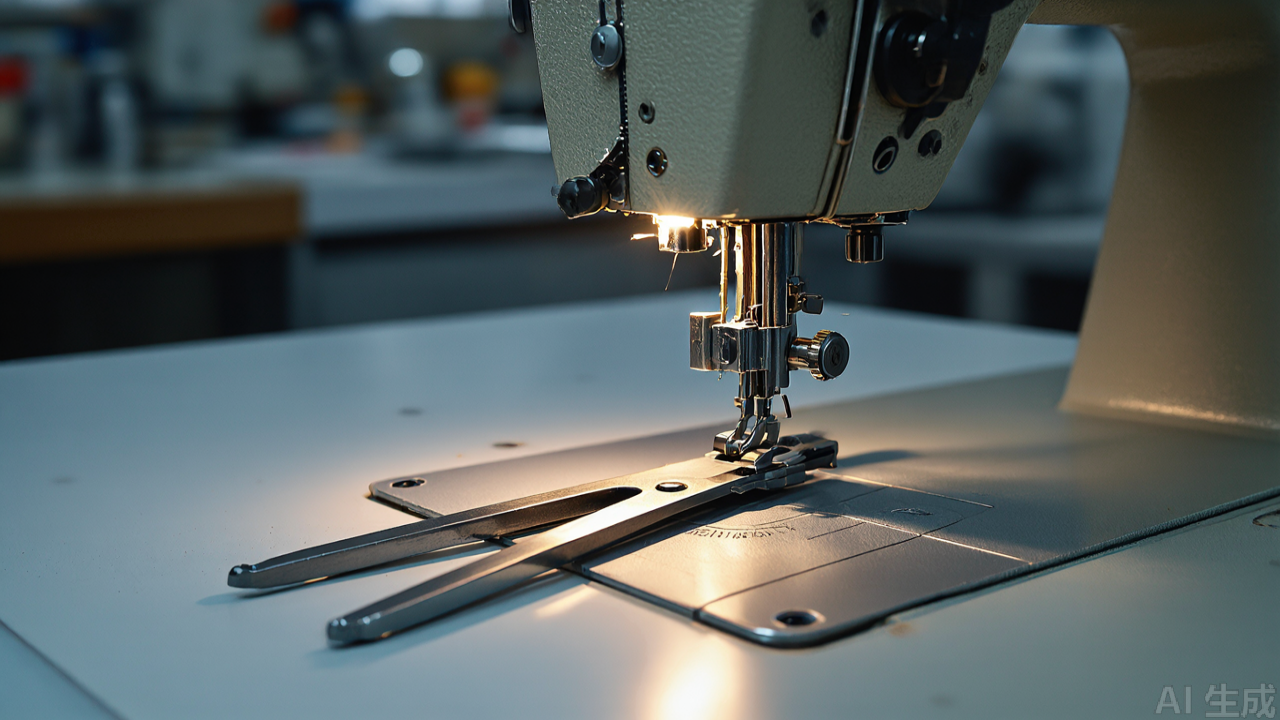
How the Double-Head Tool Works: Mechanism and Internal Structure
The tool is not a jig and not a press. It is a passive guide. Understanding that distinction matters, because it explains both what the tool can do and where it stops helping.
The Guide Slot Does the Alignment Work
The working end of the tool is a shallow channel with a flared mouth. The mouth is wider than the zipper tape; the channel narrows toward the seat where the slider rests. When the operator draws the tape through, the flared mouth gathers the two tooth rows and lifts them into a single plane. By the time the teeth reach the slider, they are already at the correct entry angle.
This is the same principle as a thread guide on a tension assembly: the guide does not pull the thread, it just removes the variable. Here, the variable being removed is the operator's finger angle.
Why Two Heads Instead of One
A single-head tool can only be cut for one tooth geometry. The double-head design puts two different channel profiles on one body:
- Head A: a wider, deeper channel for standard metal and molded resin zippers, typically 5# and 8#.
- Head B: a narrower, shallower channel for fine coil zippers and invisible zippers, typically 3# and light 4#.
The two heads are not interchangeable in use — you pick the head that matches the zipper, then use the other head as the handle. This is a practical compromise. A tool with a single wide channel will let a 3# slider rock sideways and jam; a tool with a single narrow channel will not accept an 8# metal slider at all.
Where the Slider Seats
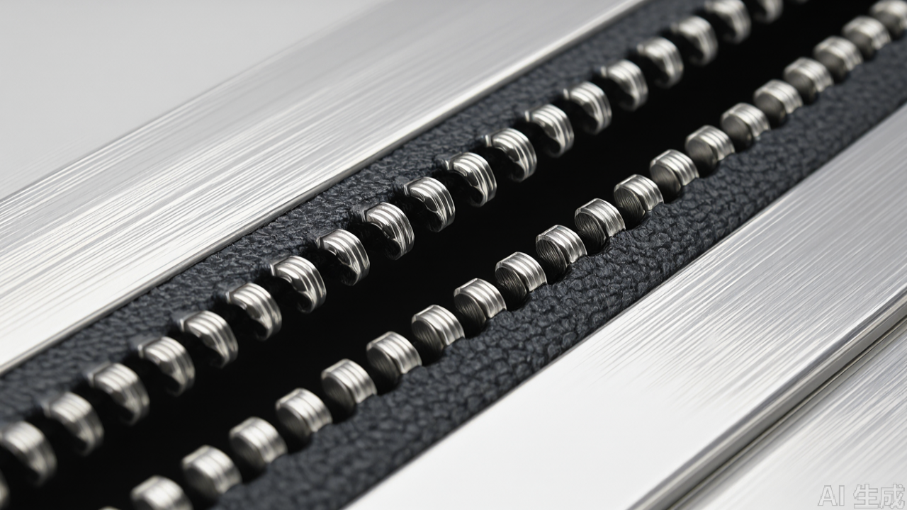
At the base of each channel there is a seat — a small step or shoulder that holds the slider body square to the channel. The slider sits in this seat with its open end facing the incoming tape. The seat is the most dimension-critical feature on the whole tool. If the seat is too deep, the slider tips forward and the teeth miss the lower slot. If it is too shallow, the slider rocks and the pull tang catches the tape.
On better tools the seat is machined, not molded. On economy tools it is molded and then hand-finished. The difference shows up after a few thousand cycles, when a molded seat wears round and the slider starts tipping.
What the Tool Does Not Do
The tool does not close the zipper, does not set the top stop, and does not replace the zipper foot on the machine. It only feeds the slider. On open-end zippers, the retainer box and pin still have to be joined by hand before or after the slider goes on, depending on the zipper type. On two-way sliders, the tool feeds one slider at a time.
Materials, Finish, and What They Mean in Production
Most tools in this category are made from one of three materials. Each has a different failure mode, and the failure mode matters more than the spec sheet.
- Stainless steel: highest wear resistance at the seat and channel edges. Heavier, and cold to the touch in winter, which some operators dislike. Will not rust from hand moisture. Best choice for high-volume lines running metal zippers.
- Zinc alloy with plating: lighter and cheaper to produce with tight tolerances. The plating can chip at the channel edge after heavy use, and a chipped edge will scratch tape. Acceptable for medium volume.
- Engineering plastic (glass-filled nylon or POM): lightest, and will not scratch tape or coating. Wears faster at the seat, and the channel edge can round off. Best for resin and coil zippers, and for sampling rooms where volume is low.
Surface finish on the channel matters as much as the base material. A polished or lapped channel lets the tape slide with light finger pressure. A rough channel forces the operator to push harder, and hard pushing is what bends teeth. If you buy in volume, ask for the channel surface finish spec, not just the material grade.
Typical Dimensions and Zipper Compatibility
Exact dimensions vary by maker, but the pattern is consistent. A general-purpose double-head tool usually measures around 80–120 mm in overall length, 10–20 mm in width, and 5–10 mm in thickness, with a weight in the 30–80 g range. The narrow head typically accepts 3# and 4# sliders; the wide head accepts 5#, 8#, and sometimes 10#.
Do not trust a nominal size label. Zipper sizes are not fully standardized across suppliers. A 5# slider from one tape mill may not fit a 5# channel from another tool maker. The only reliable check is to test the actual slider you use in production against the actual tool you plan to buy.
Step-by-Step: Feeding a Slider with the Tool
The sequence below is the standard method. It takes about three to five seconds once the operator is used to it.
Before You Start
- Confirm the slider size matches the zipper size. A mismatch is the single most common cause of jamming.
- Confirm the tool head matches the slider. Use the narrow head for 3#–4#, the wide head for 5# and up.
- Check that the zipper tape ends are cut clean and square. A frayed tape end will catch in the flared mouth.
- Run one test feed on scrap tape before starting production.
Feeding the Slider
- Place the slider into the seat of the chosen head, open end facing outward, pull tang pointing away from the channel.
- Hold the tool in one hand with the channel roughly horizontal.
- Bring the two tape ends together so the teeth interlock at the entry point, or hold them parallel for an open-end zipper.
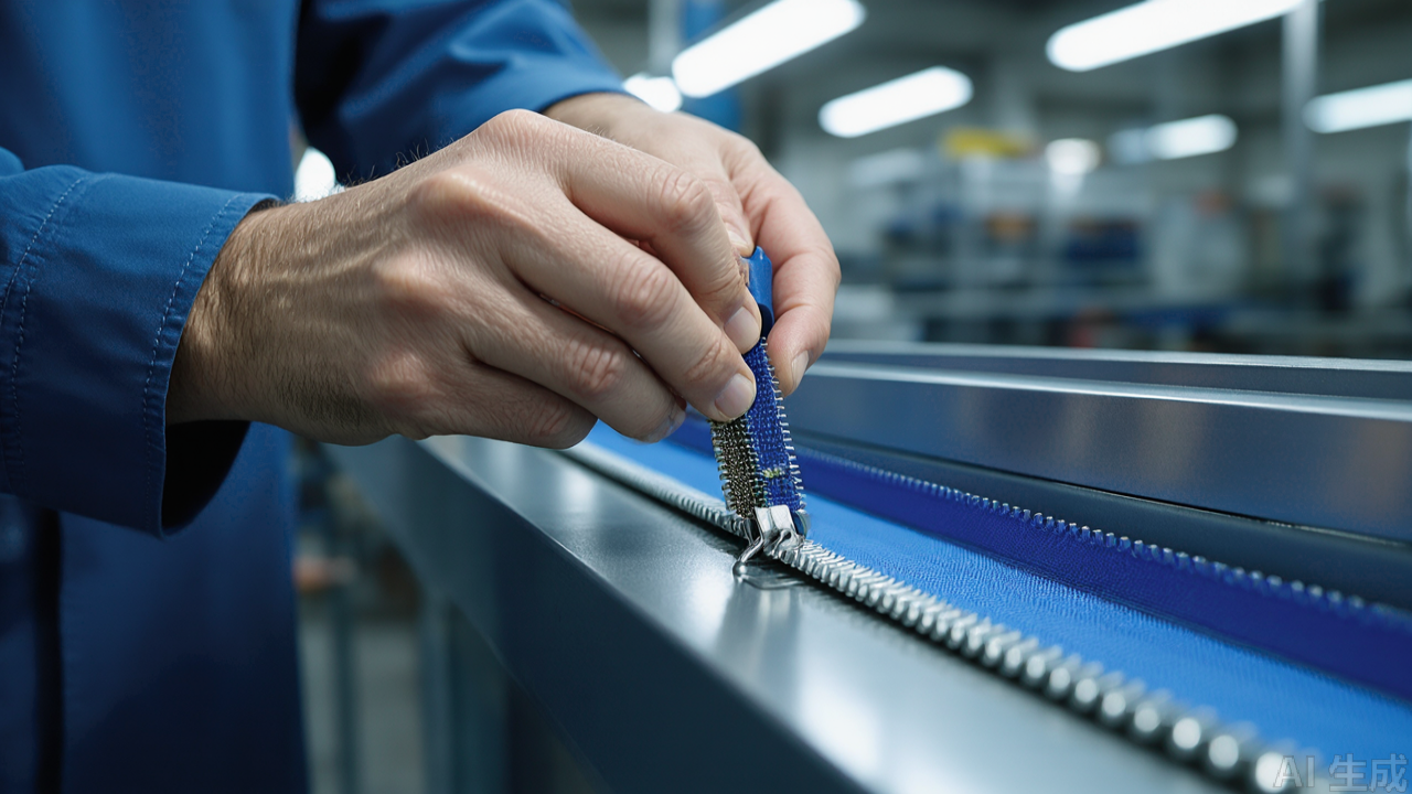
- Insert the tape into the flared mouth and push gently until the teeth contact the slider.
- Continue pushing the tape through in one steady motion. The teeth should enter both slots simultaneously.
- Once the slider is fully seated on the teeth, lift the tape out of the channel and pull the slider along the tape by hand to confirm smooth travel.
The critical point is step five. The motion should be steady, not fast. Speed does not help; a steady push lets the flared mouth keep both tooth rows aligned. A jerky push lets one row enter ahead of the other, which is exactly the condition the tool is meant to prevent.
When the Slider Is Already Sewn In
In repair work, the slider sometimes has to go on after the zipper is sewn into the garment. The tool still works, but access is tighter. In that case, feed from the open end of the zipper if one exists. If both ends are closed, the slider must be fed from the top stop end, and the top stop may need to be removed and re-set. The tool does not change this constraint; it only makes the feed itself easier.
Which Machines and Fabrics This Tool Fits
The tool is machine-independent. It is used at the bench, not mounted on the machine, so it works with any setup. That said, the surrounding process changes how useful it is.
Machines
- Lockstitch machines: the most common pairing. Zipper insertion is done with a zipper foot or an adjustable zipper foot, and the slider is fed either before or after the seam depending on the construction.
- Overlock machines (sergers): used mainly for edge finishing on the zipper tape or the seam allowance. The slider feed happens off the machine.
- Coverstitch machines: common in knitwear and sportswear where zippers are set into stretch fabric. Again, the feed is a bench operation.
- Specialty zipper machines: on high-volume lines, dedicated zipper setting machines exist. These have their own feeding mechanisms and do not need a handheld tool. The handheld tool is for lines that are not dedicated, or for rework stations.
Fabrics and Zipper Types
The tool is most valuable where the zipper is small, the slider is stiff, or the operator's hands are busy with fabric. That means:
- Denim and heavy woven: metal zippers, 5# and up. The wide head handles these. The tool saves time but the slider is large enough that hand feeding is also viable.
- Light woven and shirting: 3# and 4# coil or resin. This is where the tool pays for itself, because the slider is small and the reject rate from hand feeding is highest.
- Knitwear and stretch fabric: invisible zippers and fine coil. The narrow head is required. Tape distortion is a risk, so a light touch matters more here than on woven.
- Bags and accessories: 3# to 10# depending on the product. Cosmetic bags and small pouches are the strongest use case.
- Home textiles: duvet covers and cushion covers, usually 5# resin. Moderate benefit.
Where the tool helps least: large metal sliders on heavy outerwear, where the slider is big enough to feed by hand and the operator has good access. In that case the tool is a convenience, not a fix.
Common Mistakes and Maintenance
Most tool failures are operator-induced, not manufacturing defects. The four mistakes below account for the majority of complaints.
Mistake 1: Forcing a Jammed Feed
When the teeth catch, the instinct is to push harder. This is the worst response. Forcing the tape drives the teeth into the channel wall, deforms the tooth profile, and scores the channel. Once the channel is scored, every subsequent feed drags. The correct response is to withdraw the tape completely, check the slider orientation, and start again.
Mistake 2: Using the Wrong Head
Operators under time pressure use whichever head is facing them. A 5# slider in the narrow head will seat crookedly and jam. A 3# slider in the wide head will rock and the teeth will miss the lower slot. Marking the two heads with paint or tape reduces this error significantly on a busy line.
Mistake 3: Ignoring Tape Condition
A frayed or heat-sealed tape end is thicker than the nominal tape. It will not pass the flared mouth cleanly. Trim tape ends square before feeding. On coated tapes, check that the coating has not swollen the tape edge.
Mistake 4: Skipping Cleaning
Lint, thread fragments, and dust accumulate in the channel and at the seat. A single thread fragment in the seat will tip the slider and cause intermittent jams that are hard to diagnose. Clean the channel with a dry brush or compressed air at the end of each shift. Wipe the body with a dry cloth. Do not use solvent-based cleaners on plated or plastic tools.
Storage
Store the tool dry. Stainless tools tolerate humidity; plated and plastic tools do not tolerate solvent vapors or long exposure to damp air. Keep the tool away from the machine's oil pan and from areas where cutting fluids are used.
Selection Tips for Parts Buyers
If you are specifying this tool for a production floor, the purchase decision is not about brand. It is about matching the tool to the zipper mix on the line.
- Map your zipper sizes first. Count how many styles use 3#, 4#, 5#, 8#, and above. If 80% of your volume is 3#–5#, a standard double-head tool covers it. If you run 10# metal regularly, confirm the wide head actually accepts it before ordering in volume.
- Ask for the channel width tolerance, not just the nominal size. A tool labeled "fits 3#–8#" may fit all of them loosely. Loose fit equals jams.
- Test with your actual sliders. Send sample sliders to the supplier, or order a small trial batch and run it on the floor for a week. Zipper size labels are not reliable across mills.
- Match material to volume. Under about 500 feeds per day, plastic is fine. Above that, stainless steel pays back quickly at the seat.
- Order spares. These tools are small and get lost. A line running three shifts should hold at least one spare per station.
- Check the finish on arrival. Run a finger along the channel edge. Any burr or rough spot will scratch tape and should be returned.
For buyers sourcing factory sewing parts in volume, the practical approach is to standardize on one or two tool models across the floor, so operators do not have to think about which tool to pick up. Standardization reduces the wrong-head error more than any marking scheme.
Where This Tool Fits in a Broader Parts Strategy
Zipper feeding tools sit in the same category as seam guides, magnetic guides, and binder attachments: low-cost accessories that remove a specific, repeatable manual difficulty. They are not machine parts in the sense of a feed dog or a needle plate, and they do not affect stitch formation. Their value is entirely in labor time and reject rate.
For a line manager, the calculation is simple. If a station feeds 800 sliders a day and the tool cuts two seconds off each feed, that is roughly 27 minutes of labor per station per day, plus the reduction in rework from bent teeth and damaged sliders. Against a tool cost measured in single-digit dollars, the payback is short. The tool is not a solution to a quality problem that starts elsewhere — if your zipper tape is out of spec or your sliders are inconsistent, the tool will not fix that. But for the specific, narrow problem of getting a slider onto a tape without damaging either, the guide-slot mechanism is effective and the double-head format covers most of the size range a typical garment or bag factory runs.
When specifying industrial presser foot components and related bench accessories, treat the zipper feeding tool as a consumable, not a durable. Buy it in small quantities, test it against your actual slider mix, and replace it when the seat wears. That is the honest way to get value from it.
Need this part for your workshop?
Get a Free Quote on WhatsApp: +86 137 3825 6697Browse the full catalog at pinseam.com · Free 2026 full catalog (PDF) · Related guide: industrial presser foot
📢 New arrivals & factory updates on Telegram — join our channel
Edited by the technical team at PL (Professional Leader) — high-quality sewing machine accessories from China. About our factory | Catalog: pinseam.com | WhatsApp: +86 137 3825 6697 | Telegram: @plsewingparts
Explore Our Parts Guides
- sewing machine accessories, needle threaders & thread guides
- industrial & magnetic seam guides
- presser foot guide: types & compatibility
- industrial presser feet for factory lines
- roller & rolled hemmer presser feet
- industrial sewing machine parts & spare parts
- wholesale sewing machine parts, factory direct
- about PL (Professional Leader)
Questions about a specific part? Chat with us on WhatsApp +86 137 3825 6697 — factory direct, reply within hours.


Comments
Post a Comment